XBox 360 Controller Advanced Rapidfire Mod
advanced firing modes, variable sensitivity, microcontroller based, diy
Motivation#
Of course, there are several rapidfire mods on the web but most of them doesn’t work as exceptet: they only operate in a few games, they are traceable by the game software, you have an addiotional inconvenient firing button with a longer responsetime as the normal trigger, and so on.. With this mod you didn’t have such problem anymore!
Benefits#
- Binded to the RT Trigger – no additional firing button – this will significant increase your responsetime ! when rapidfire is enabled you can normally press the RT button – this will trigger the burst
- Variable Trigger sensitivity – imagine you only have to press the trigger about ~1mm instead of ~7mm to trigger firing. this also significant increase your responsetime
- Different Firing Modes, at the moment (firmware 1.1) Off, Slow, Fast – addicted to your game it is neccesarry to have different firing speeds because some games want to prevent the usage of rapidfire controllers – with this mod this is not a problem anymore !
- Automatic Trigger calibration – get the maximum sensitivity in rapidfire mode – no manuel setup needed
- OpenSource – you need a custom firmware/functions ? do it !
- Uses digital signal processing with random-time-algorithmens – it is not traceable by any game/software like other mods
- Hardware costs under 10€
- Ultra leightweight controller: force feedback drives get removed (you can also retain them)
Comparison#
First of all, here is a simple block diagramm based comparision between the mostly used rapidfire mods, including there functionality and disadvantages.
Default Operation#
In normal operation mode the trigger is connected rotary potentiometer which will work as an voltage divider. It generates a voltage between ~1.4V (released) and ~0.2V (pressed) depending on the trigger position. The signal gets directly processed by the usb controller chip on the mainboard.

“PWM-LED” based Mods#
The LED based rapidfire mod adds an additional signal to the analog trigger signal, when you’re pressing the rapidfire trigger. This method has many disadvantages:
- The PWM frequency is to high – RapidFire will not work in games with a rapidfire protection (trigger frquency limitation) such as ModernWarefare3..
- You need an addtional trigger for the rapidfire functionality, which is mostly bad accesable.
- The PWM signal is “hard” added to the trigger signal line, which will physical short the circuit and can cause hardware damages. This only works because of very small currents on the signal line..
- Based on the “digital” PWM signal, the rapidfire mode is traceable through the game software because it generates extremly fast trigger-down-times (it’s is like you press the trigger within 1/1000second!

Microcontroller based Mods#
The most microcontroller based mods (or based on an NE555 timer) will generate a much slower PWM based output, which is similar to the human triggering speed. In addition most of the mods will use a random time in between the simulated trigger presses like a human. This is great but you need a additional trigger and the mod is traceable by analysing the signal form of the trigger!!
Disadvantages#
- Generates a traceable digital signal (it is like you press down the trigger within 1/1000 second or more).
- Injects their signal directly into the trigger signal line like the LED mod
- Additional Trigger

The Theory behind#
Digital Signal Processing#
Basical this mod works as a digital signal processor: it captures the trigger output and generates a modified waveform depending on the current operation mode. The ouput of the signal processor is directly connected to the xbox-controller mainboard. An additional key-switch is used to select the operation mode:
- Normal Operation (RapidFire OFF): The input signal is directly passed through to the output – it works as an normal controller
- SlowRapidFire Operation: By activating the RapidFire mode the microcontroller will modify the trigger signal. By pressing the trigger generates a signal which is similar to pressing the trigger multiple times in a row (4 times a second). On releasing the trigger the controller also simulates a released trigger.
- FastRapidFire Operation: This mode is similar to the SlowRapidFire mode but it simulates 8 trigger presses a second
The big advantage of this method is the response time and the usability of your controller: nothing will change, you use your RT-Trigger for firing. The mod is absolutely not traceable because the signal processor will exactly generate a signal form which is totally equivalent to a manual press down of the trigger. In addition, random time algorithms are used: every generated trigger press is individual.

Schematics#
The design is kept simple as possible: it consists of an Atmel AVR Attiny25 microcontroller with an integrated analog-digital converter and a PWM(pulse width modulation) output. With the attached 2. order low-pass filter it works as an digital-analog converter. For security reason an voltage divider is added to the output stage to limit the voltage to a maximum of ~1.6V. This will avoid accidental hardware damages on software failures.
To build an copy of the PCB you need basic electronic knowledge and some experience how to program AVR microcontrollers. It is recommend to use an socket for the AVR microcontroller.

DIY Tutorial#
1. Preparation#
You need a few tools to enforce the mod:
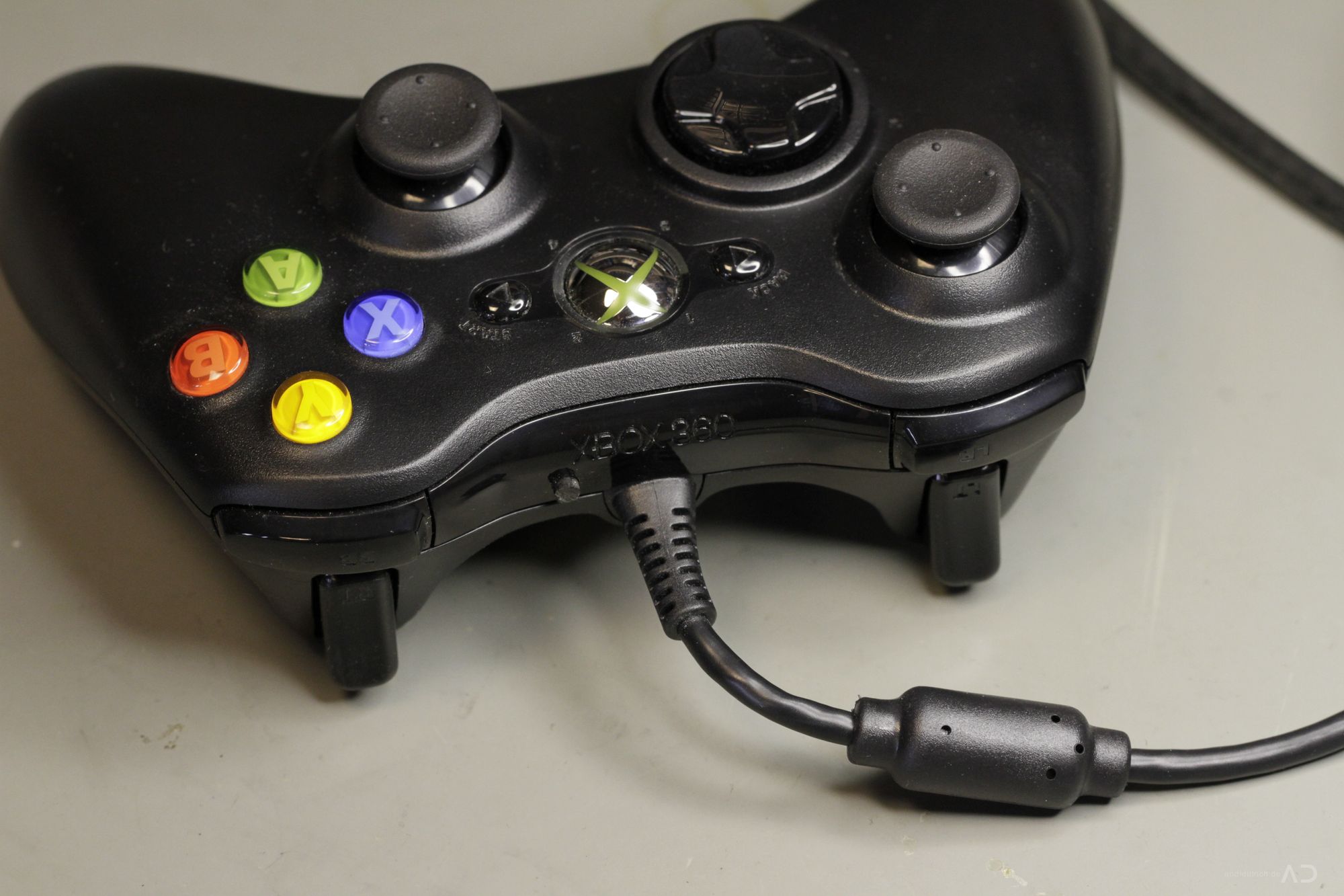
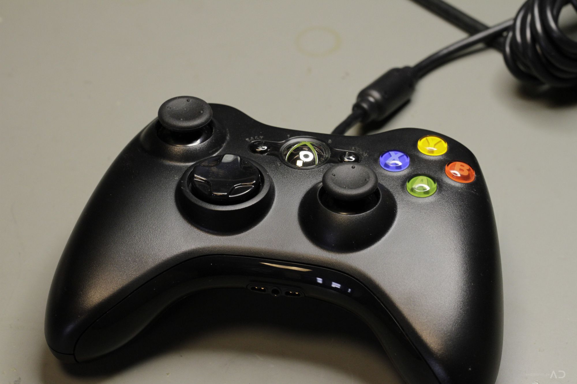
- Original XBox 360 Wired! Controller (Wireless is also possible but it need’s some hardware+software modification -> no 5V power supply avaible!)
- Soldering Iron with a fine tip (temperature controlled ~280°C)
- Fine solder and flux
- Small diagonal pliers
- Phillips and Torx Screwdrivers
- Some wires ~ 0.14mm²
- 3mm LED of your prefered color (activity indicator, behind the guide button)
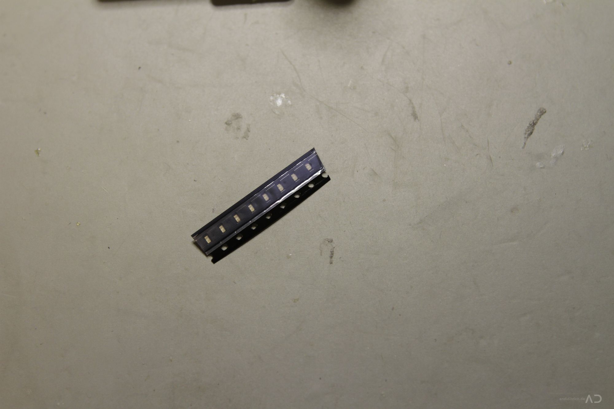
- Optionally four 0603 SMD LEDs for the LED Mod (i take some from Osram)
- Rubber Tape
- Switch Key
- Glue: instant adhensive and epoxy resin
- AVR Attiny 25 Microcontroller (DIP Package)
- AVR programming device (i use an STK500)
- Capacitors: 2*100nF X7R Ceramic, 2.54mm
- Resistors: 10k, 3k3 in 0805 SMD, 10k, 150R (LED) in THT
- Prototyping Breadboard
- About 4hours of time
- Excellent soldering skills
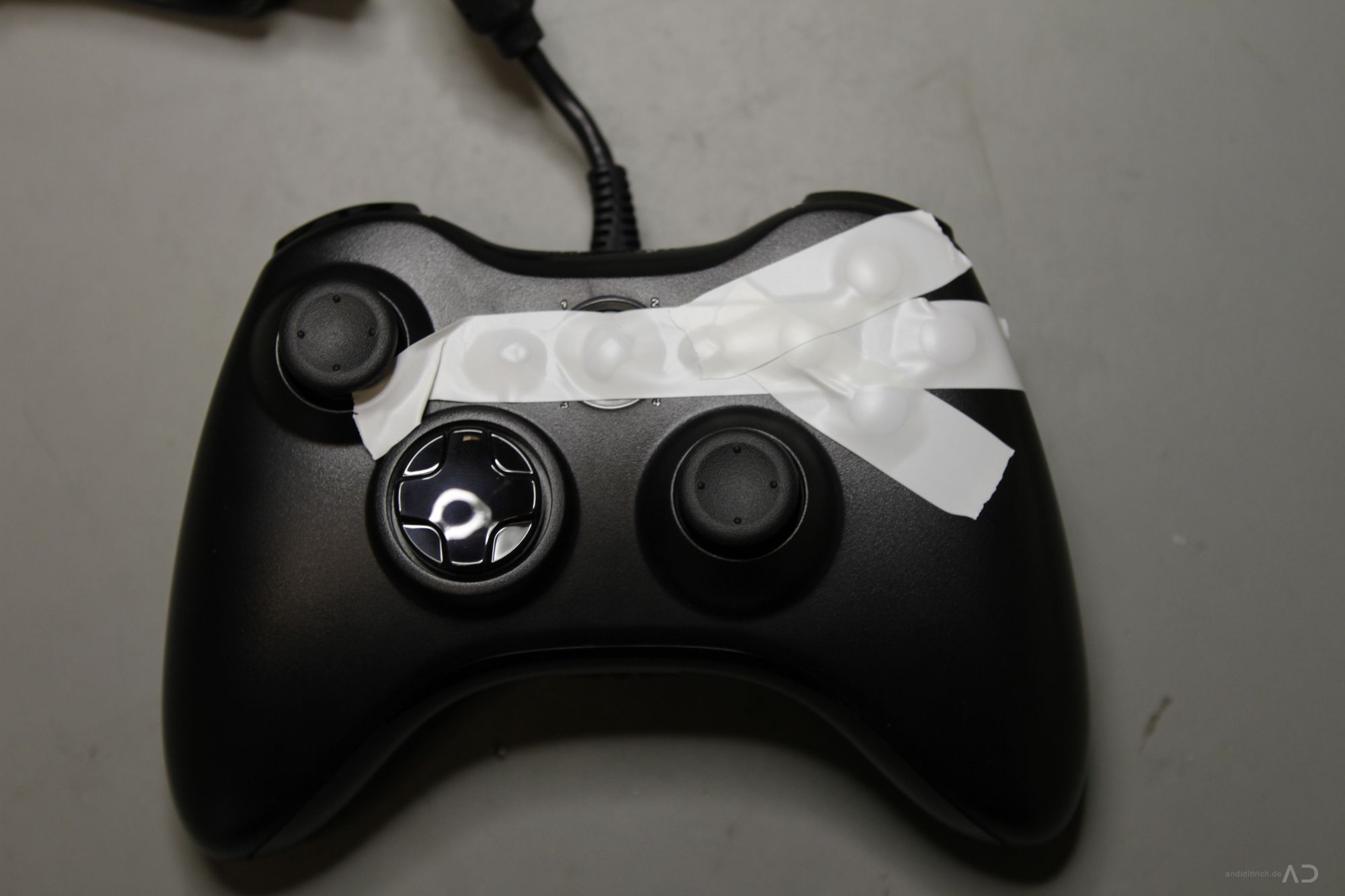
2. Disassemble the Controller#
First of all you have to disassemble the controller by unfasten the 7 screws on the bottom side of the controller. Before doing this it is recommend to fix the buttons on top with some electric tape or something similar!

3. Open the case#
Carefully open the rear side: only remove the case, keep everything in place!
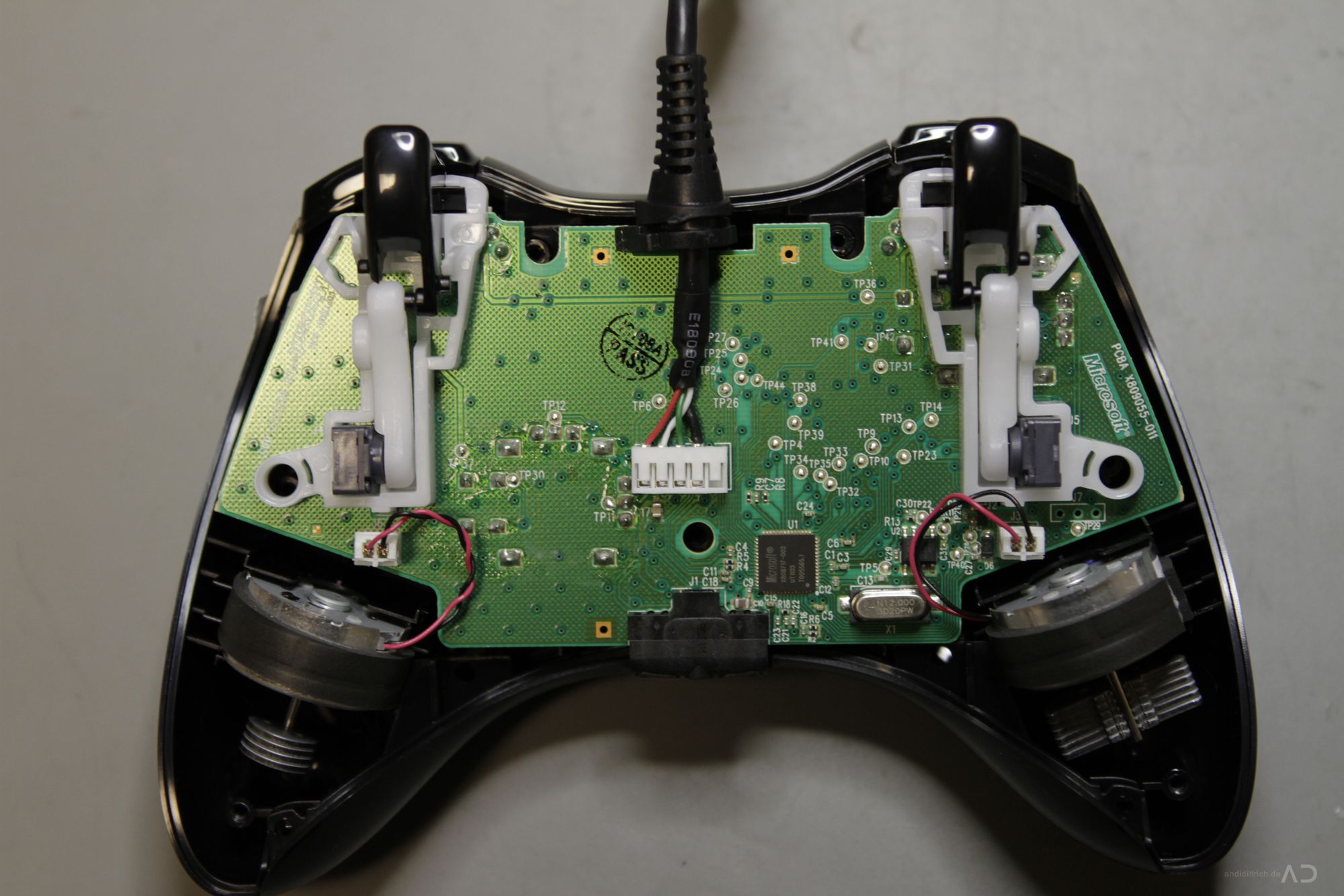
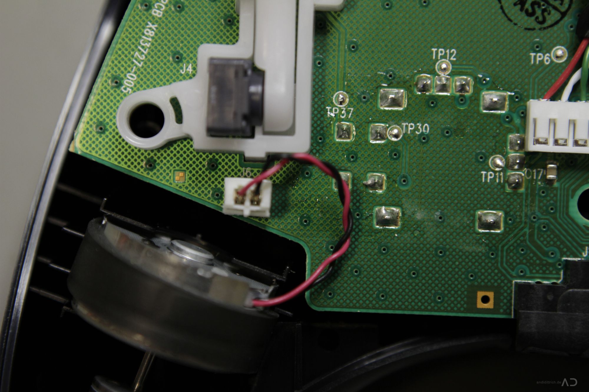
4. Removing the force feedback drives#
Do you like force feedback ? No ? then remove the drives on the left and the right side. Pull out the 2-pin molex connectors, then you can easy remove the drives – they are not mounted! Finally you’ve get an ultimate lightweight controller.
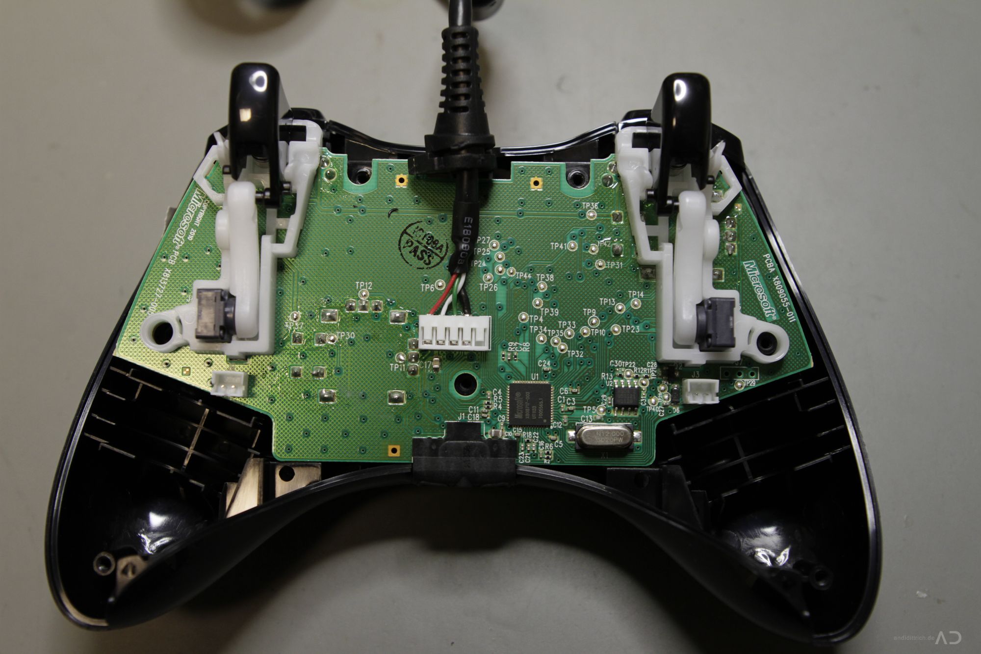
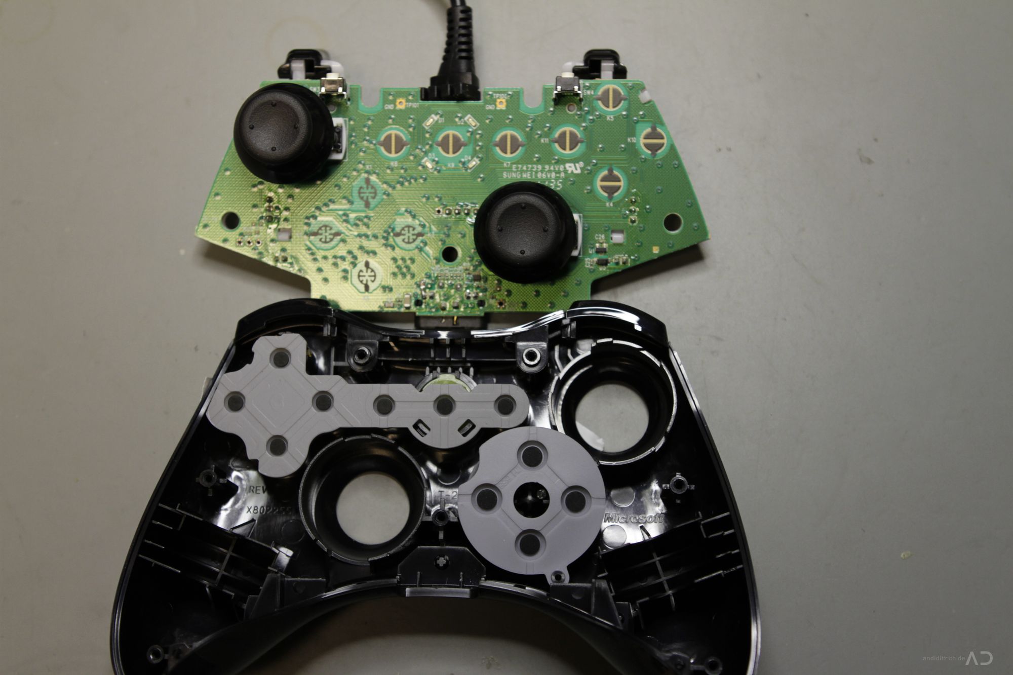
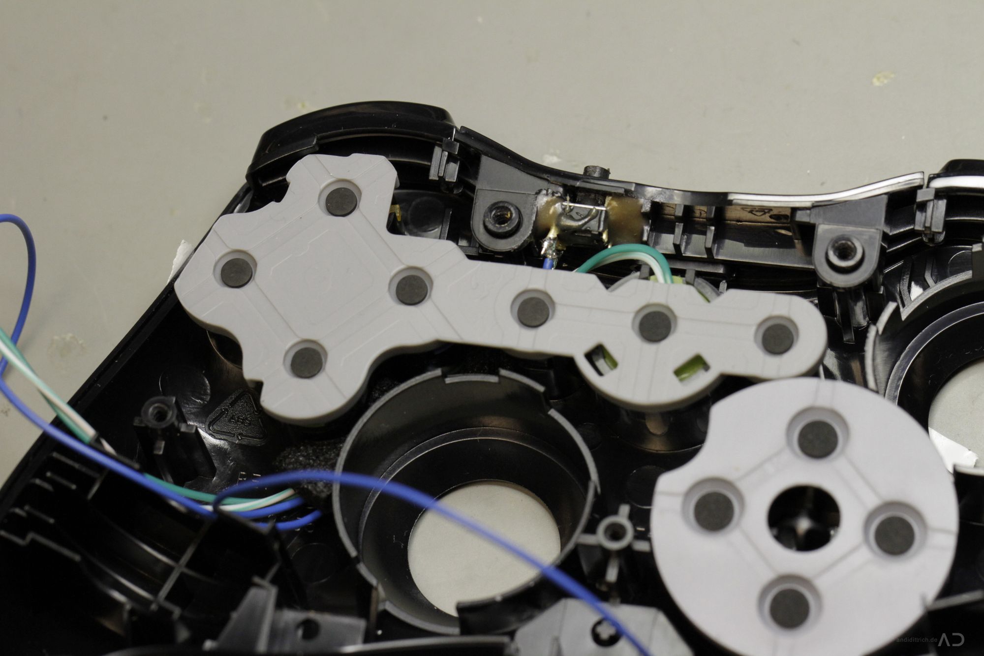
5. Remove the PCB#
Now just extract the PCB – it is not mounted. Keep the rubber pads in place.
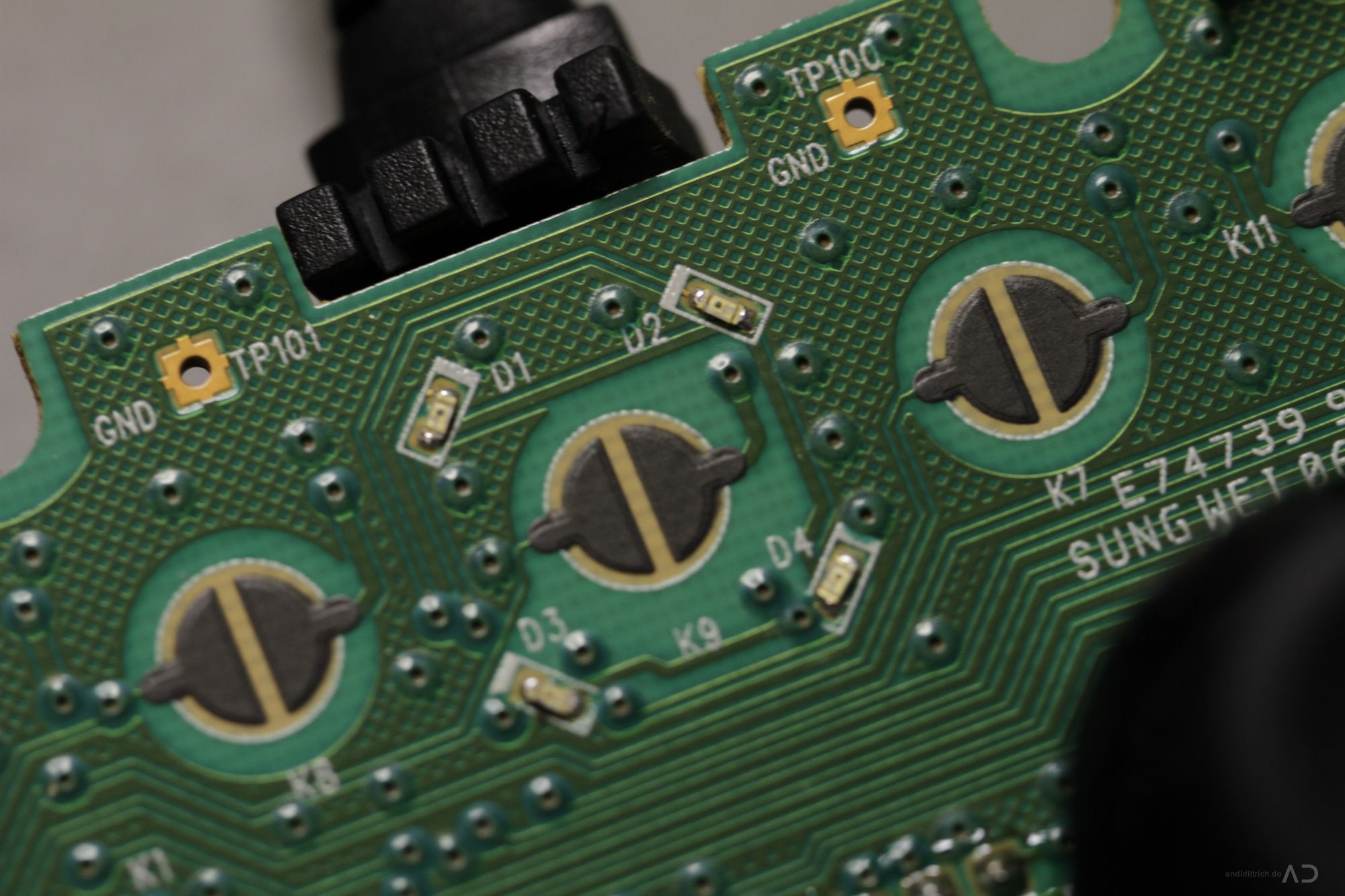
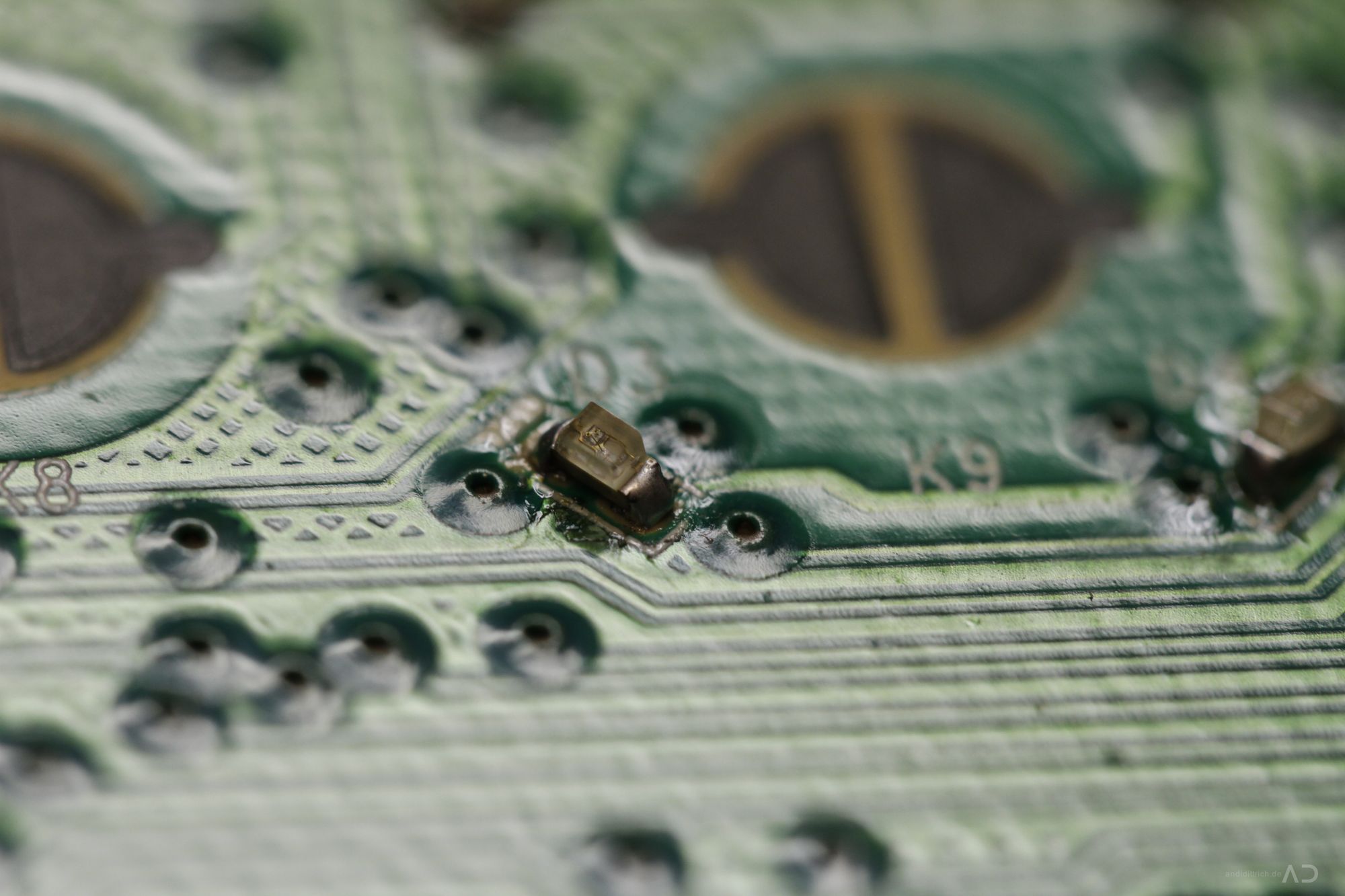
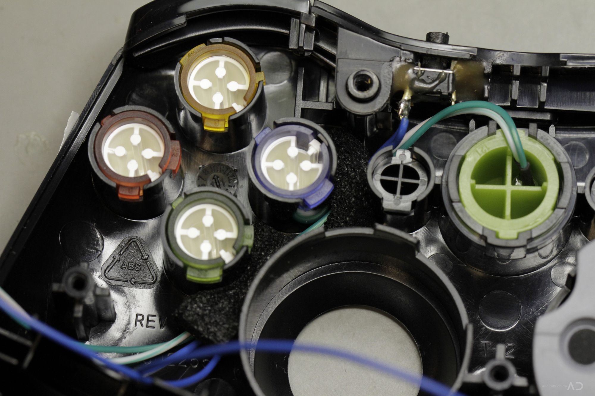
6. LED Mod (optional)#
You don’t like the green LED ring ? Change the LEDs and get happy. For this step you need some new SMD 0603 LEDs e.g. in blue, white or any other color (I’ve used some 0603 Smart LEDs from Osram. Theoretical you cannot change LEDs of different colors because all LEDs have a different forward voltage and the circuit board has to be changed (other resistors, other current, …). But in practice it works without any modifications (at the moment i didn’t have reverse engineered the pcb – i believe the LEDs are current or pwm controller). When you need a detailed description for doing an led mod just search on the web, i think it is to easy so i will not explain it – take a look at the pictures, it should be enough. After replacing each! LED you should test it.

7. Attach the Switch#
Well..this is the most sensible part – if you do it wrong, your controller will look bad outside ;) So take enough time and you will do not make any mistakes! I used a simple switch-key with a shaft diameter of 3.6mm. You should use a drill with a bigger diameter like 3.7 or 3.8mm for optimal results.
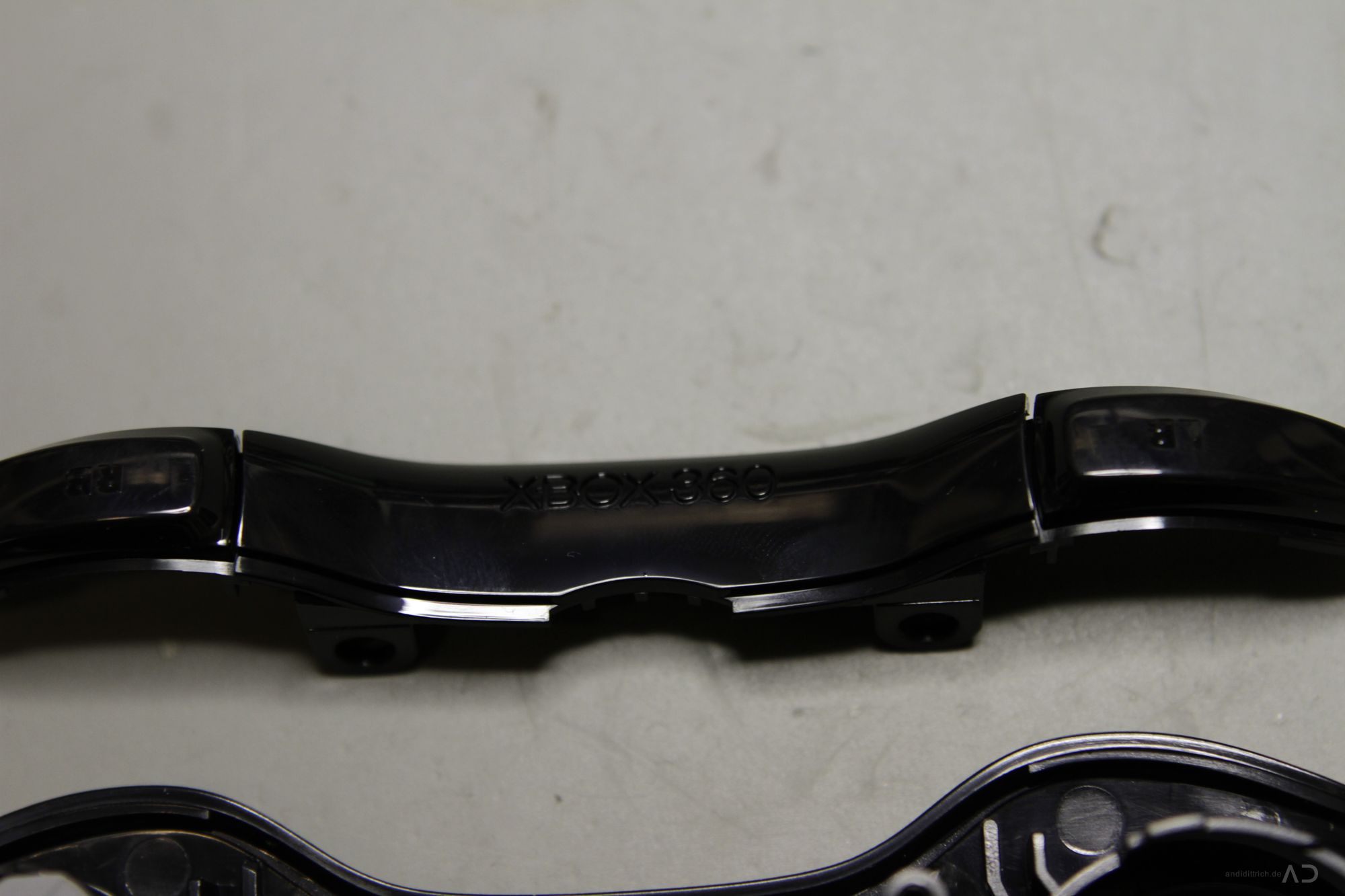
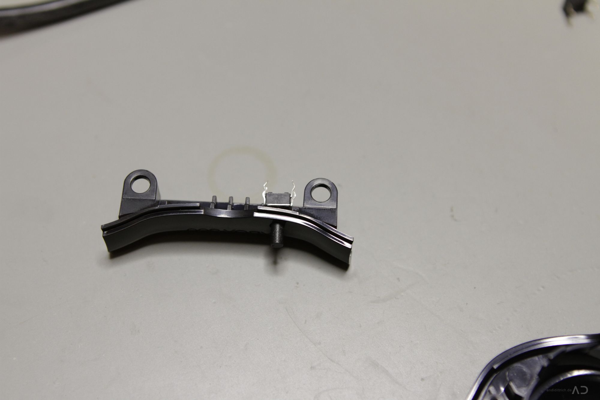
First of all you should disassemble the complete module with the RB/LB buttons – it consists of 2 parts: the buttons and it’s carrier – the hole for the button has to drilled into the carrier part.
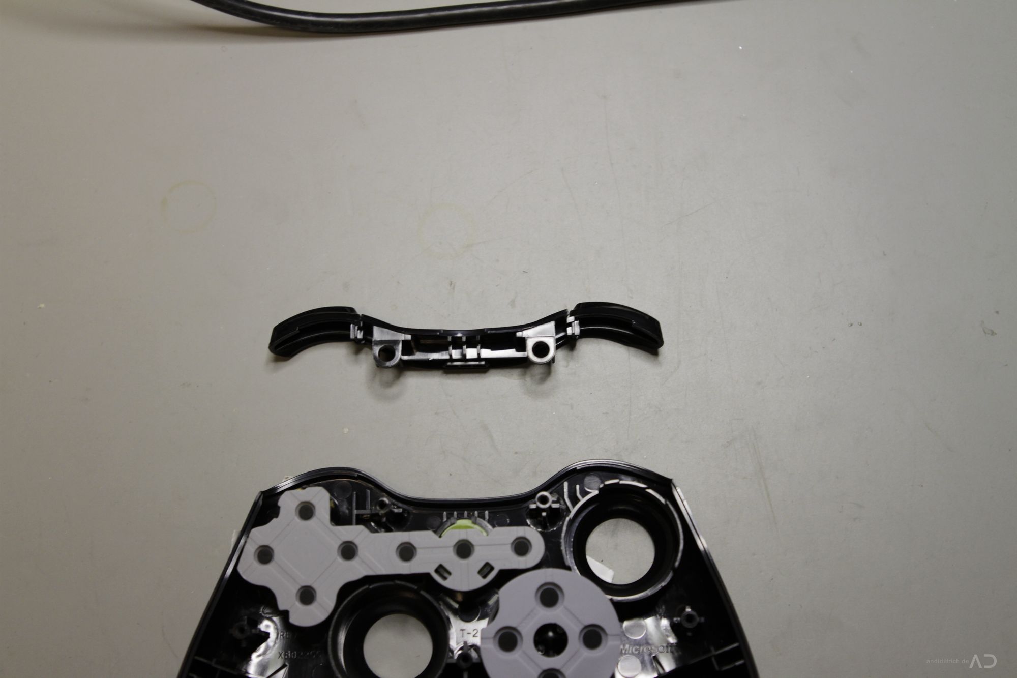
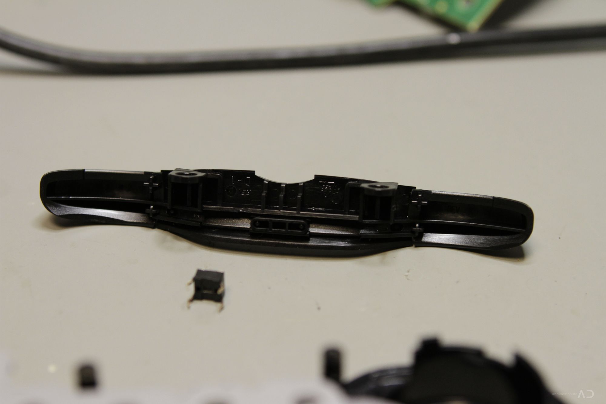
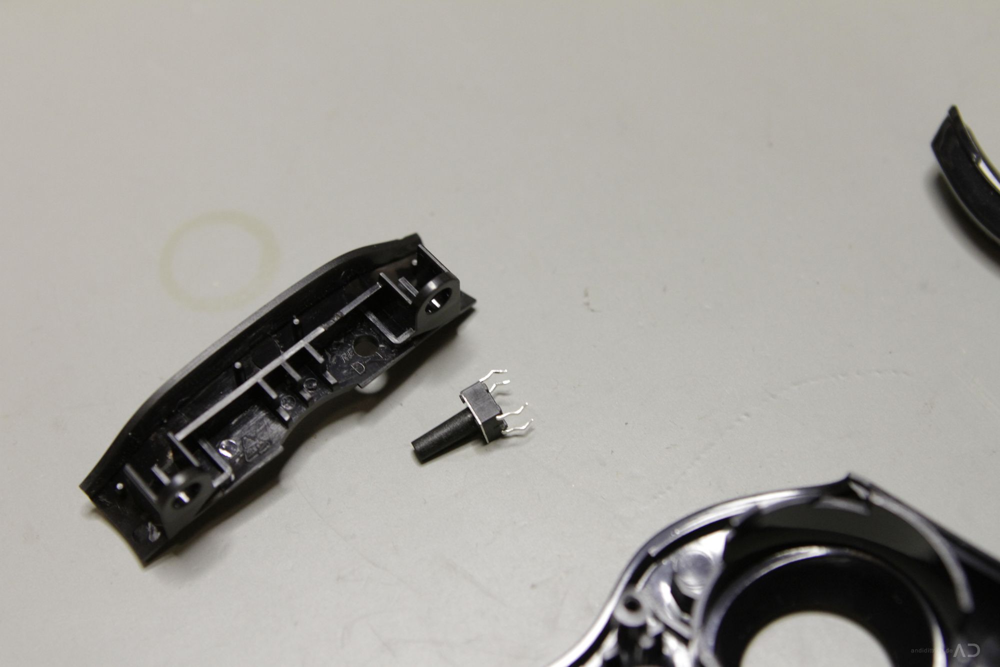
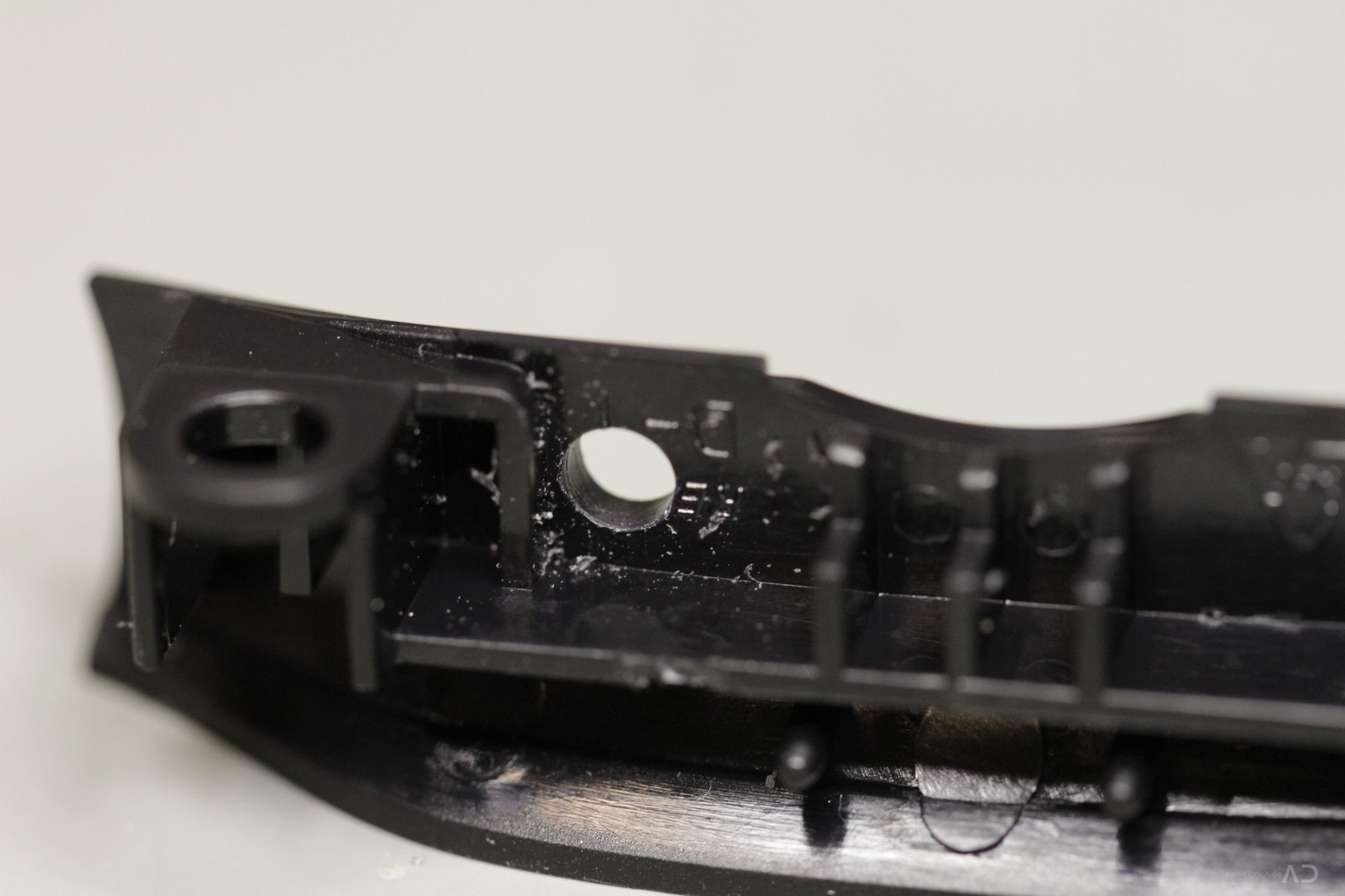
It is very important to start the drilling from inside and use some rubber to protect the outer face of your controller – otherwise the plastic case will break !! and please drill slowly.. i’ve started the pre-drilling with 1.0mm and go one with 3.7mm – this will work fine. The position of the hole should be similar to this image: the case of the switch should exactly touch the plasting bracing in center.
Drill the hole#
[singlepic id=20 w=320 h=240 float=none]
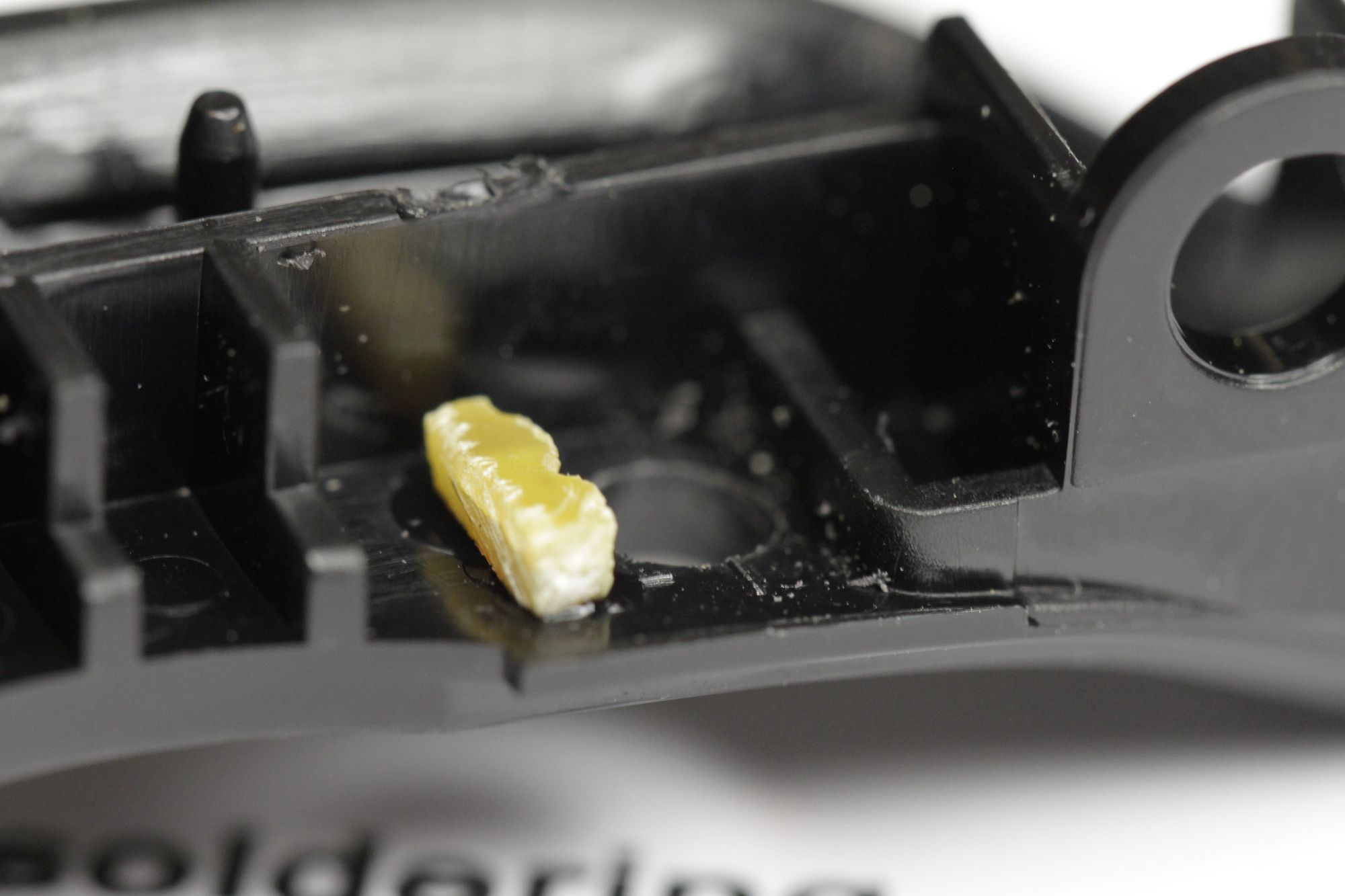
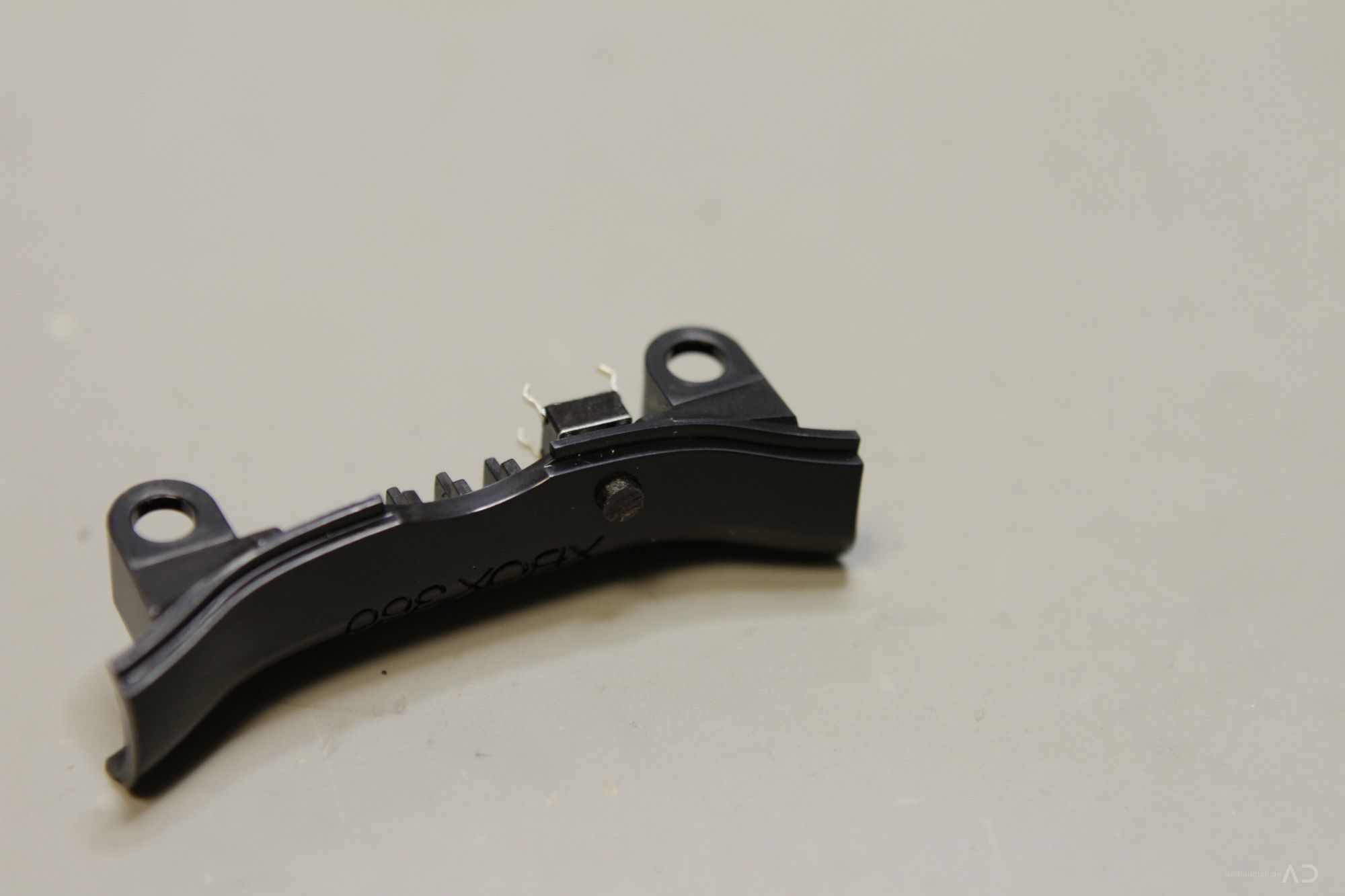
After drilling you have to fix the switch and it should be solid! Therefore i have used a two comonent based epoxy resin. But before doing this it is strongly recommended to position the switch first. To get more stability i’ve used a small peace of a prototyping pcb (1.6mm FR4) to get an horizontal “base” for the switch and fix it with instant adhensive glue in two steps: first fix the spacer then the switch!
Notice: Don’t use to much glue, otherwise it could flow into the switch and damage it permanently !!
Fix the switch temporary#
[singlepic id=24 w=320 h=240 float=none]
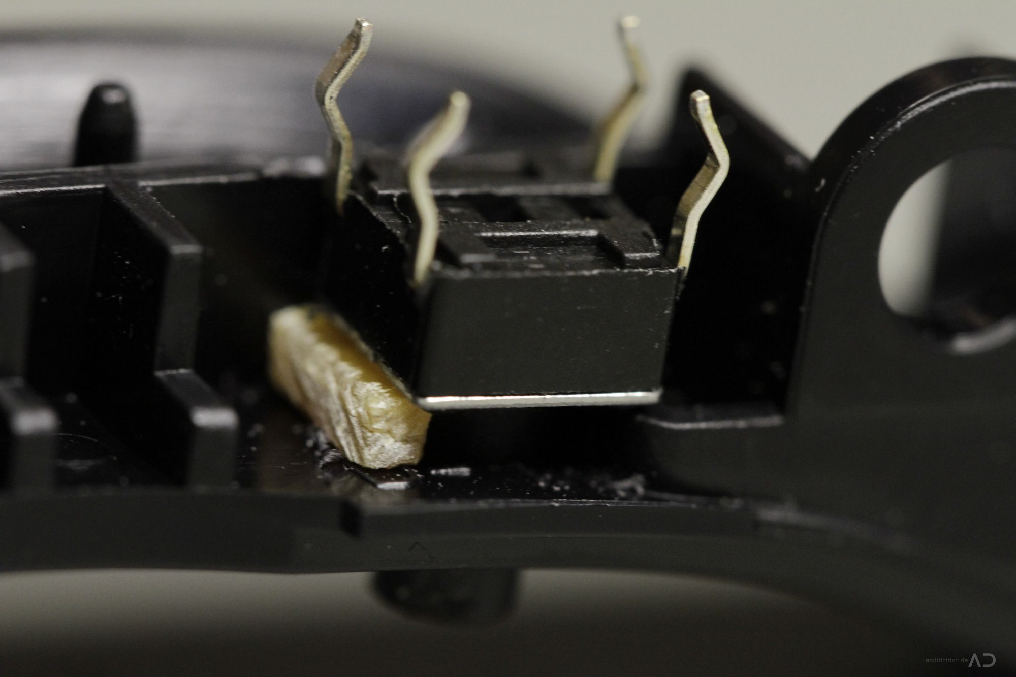

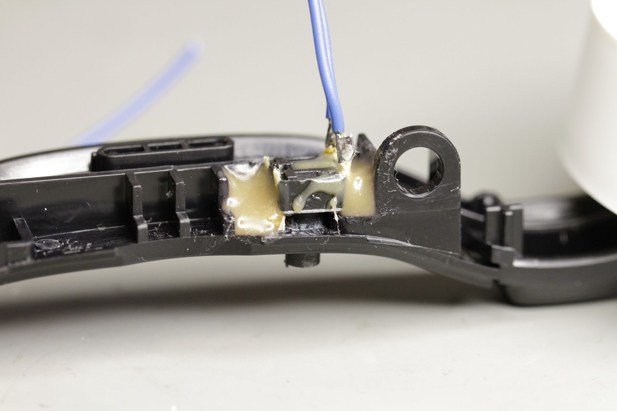
It will take about 60seconds until the glue is solid. Now you can use epoxi resin to get an solid connection between the switch and the plastic base. It doesn’t have to look nice..it is inside..nobody will see it ;) Depended on the epoxy resin type it takes minuttes to houers until it is totally cured. After this you have to solder two wires on the switch. Keep them at least 20cm long! Finally mount the RB/LB buttons on the carrier and attach the complete module to the controller case.
[singlepic id=25 w=320 h=240 float=none]

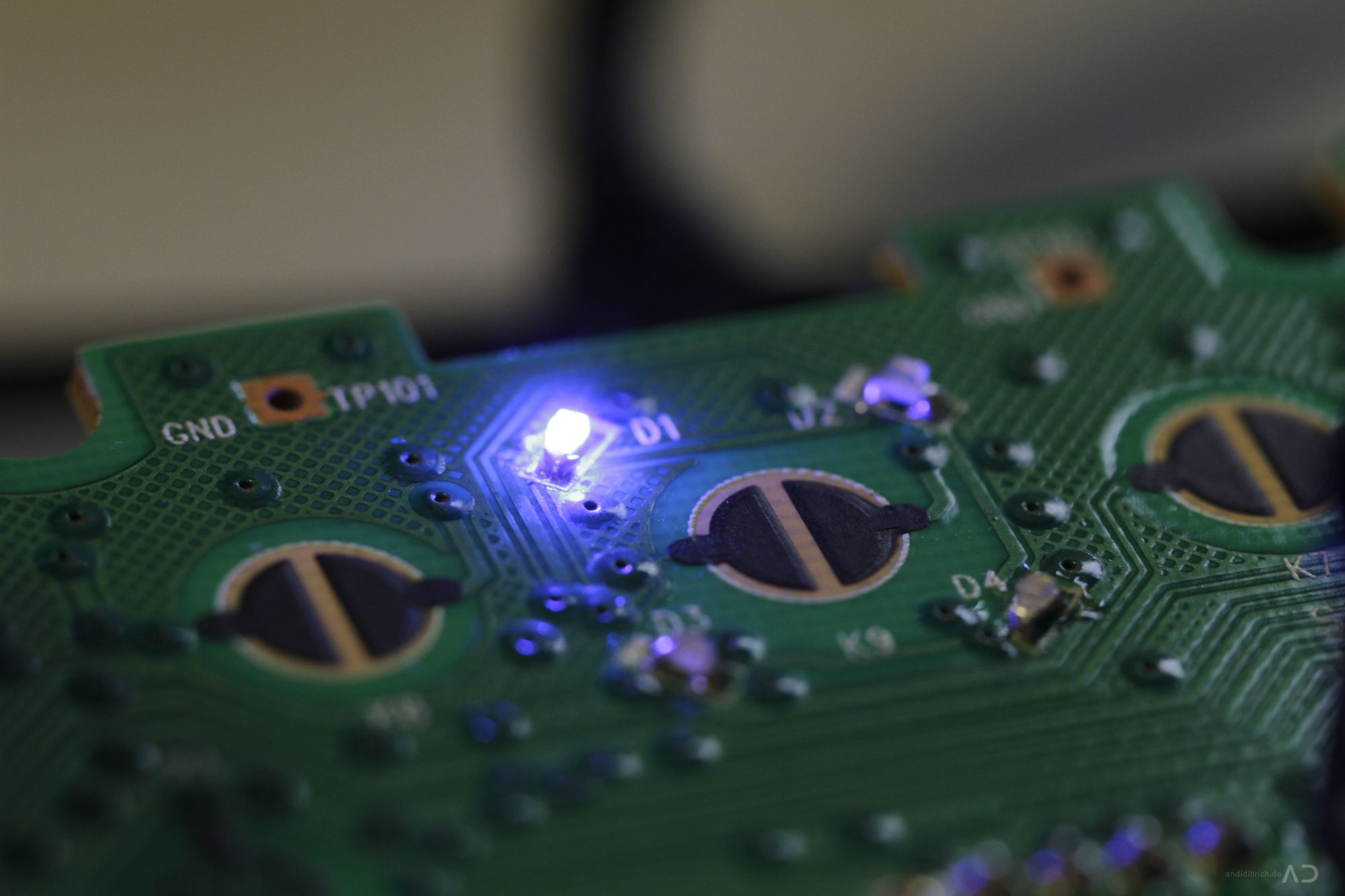
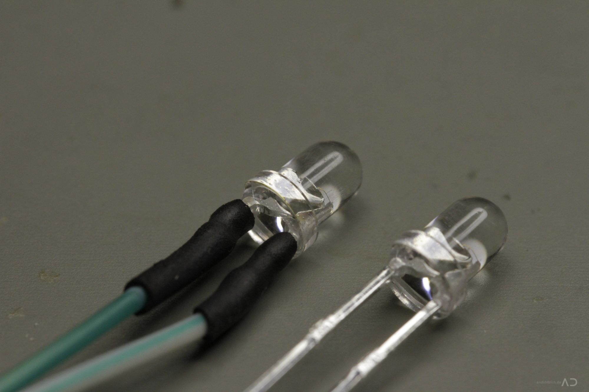
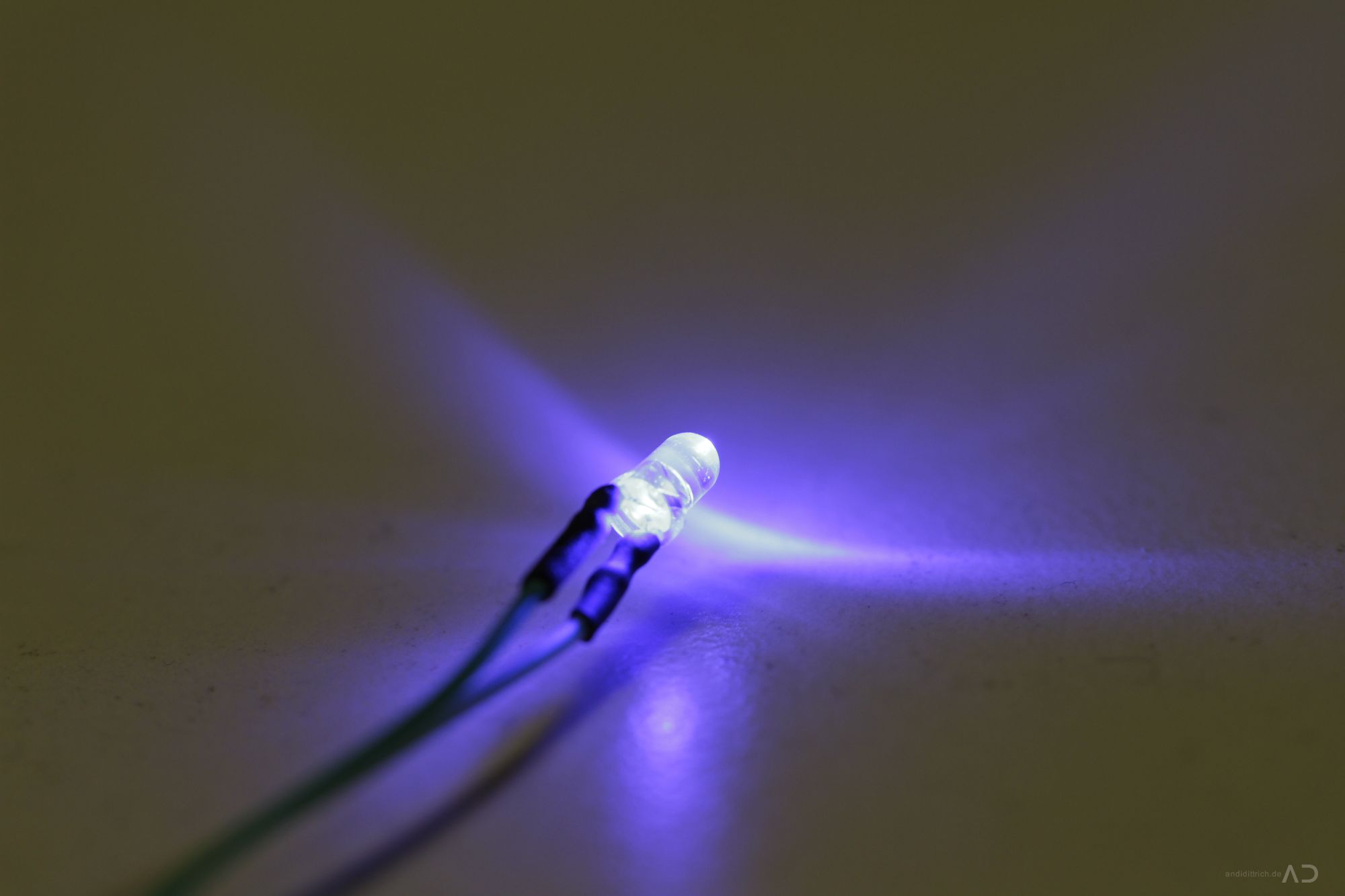
8. Install the Activity-LED#
A LED is used to indicate the current rapidfire status of the controller (off:led_off, rapidfire_slow:led_slow_blink, rapidfire_fast:led_fast_blink). You can use an arbitrary position e.g. next to the right stick. But the imao most elegant method is to use the status led as an backlight of the guide button – it’s very simple and you didn’t have to drill again. A 3mm LED will optimal fit into into one of the sections of the guide button, but you have shorten the LED connection pins to about 5mm, otherwise the button will not work again.
I have tested it with some high-power green LEDs (15.000mCd) and on maximum power it was so bright, that you get blinded – so i recommend to use such LEDs only on 10% of power or less!
[singlepic id=32 w=320 h=240 float=none]
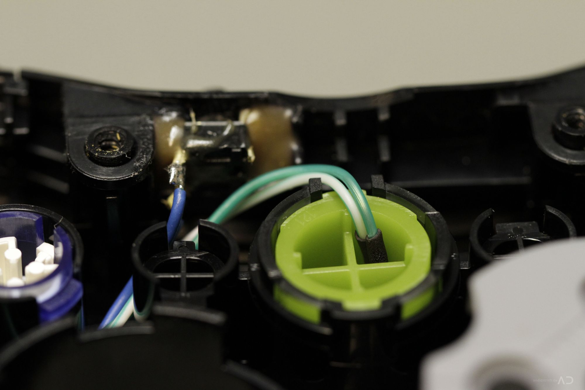
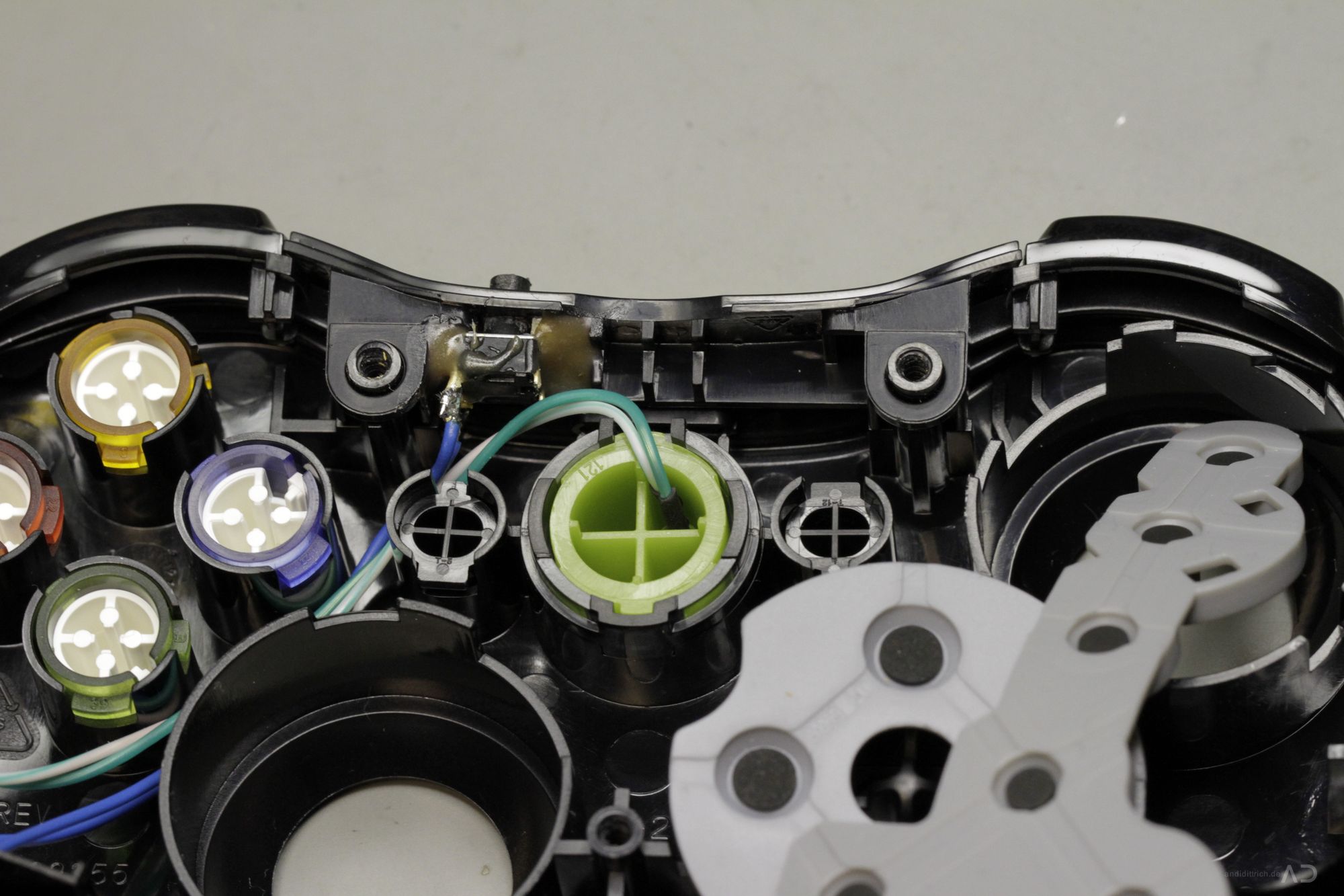
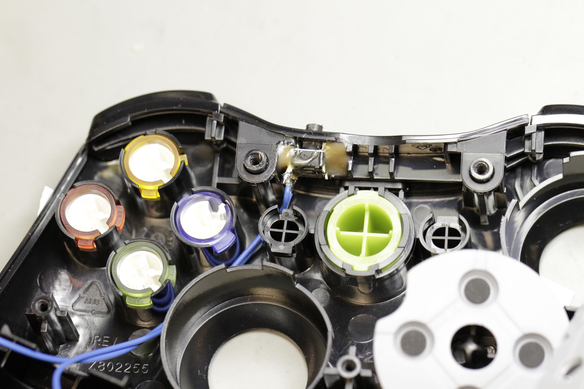
The wires of the LED have to left the guide button housing on top and go in parallel with the switch-key wires. You can fix them with glue on the case but is it not necessary (i’ve didn’t done this). Be aware of to much tension on the wires! After this you can reattach the rubber-button-pad.
[singlepic id=35 w=320 h=240 float=none]
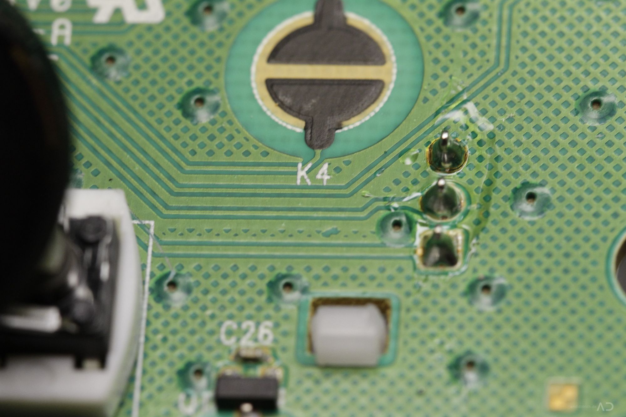
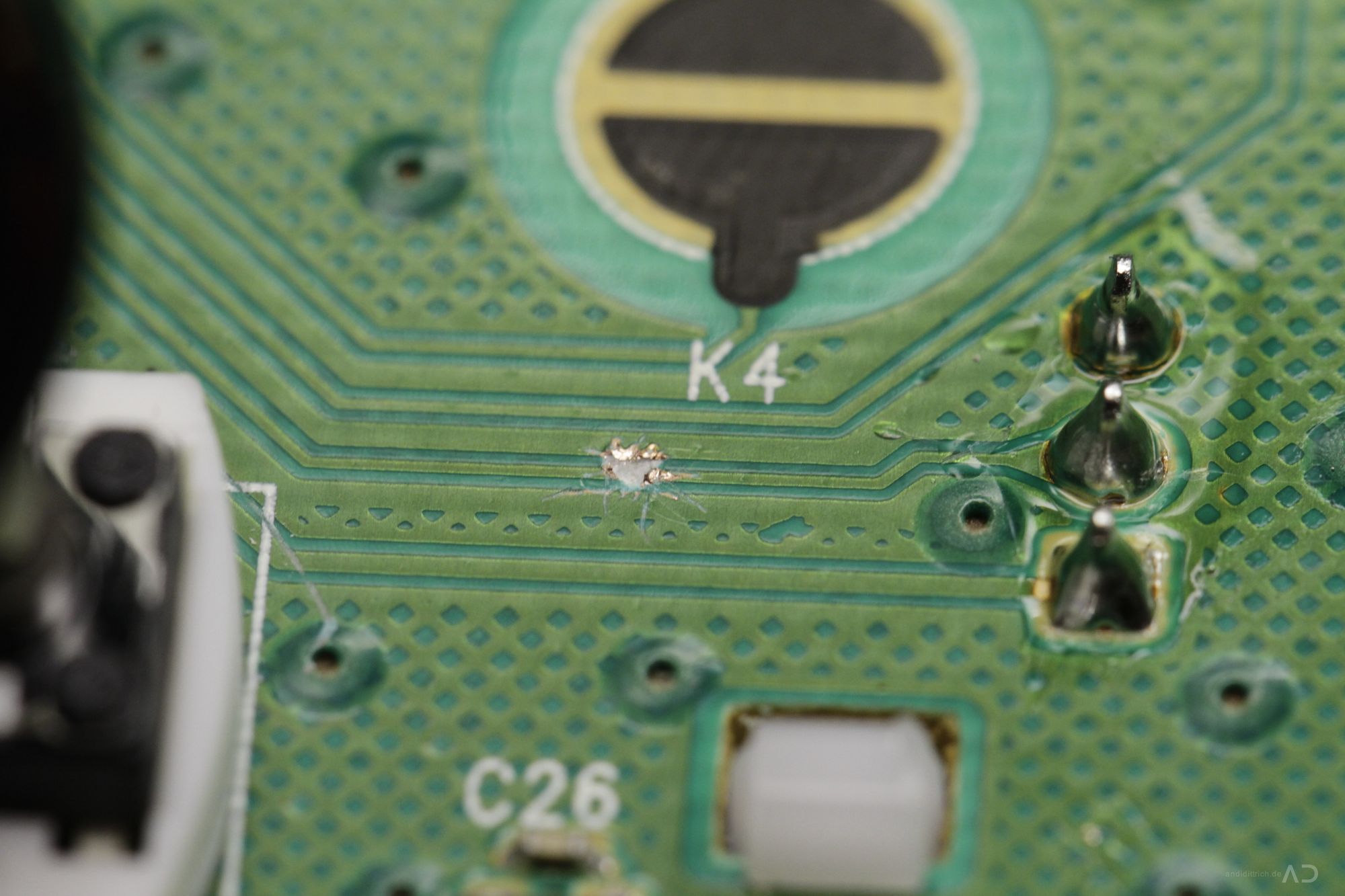
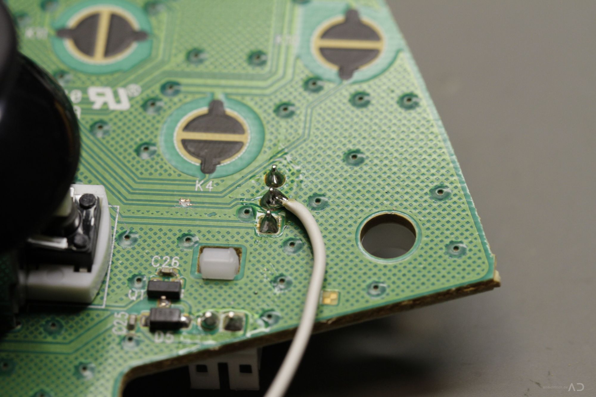
9. Break the Trigger Connection#
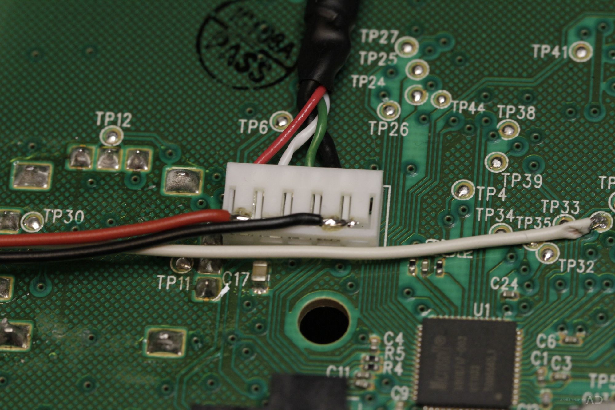
To integrate the microcontroller in between the trigger and the mainbaord you have to break a connection on the pcb. To do this i have used a very sharp scalpel and a small screw driver. The connection is diretly under the A-button – the strip line is connected to the center pin of the trigger-poti. The disruption should be about 1mm long to ensure the correct rapidfire functionality.
After breaking the track a wire has to be soldered to the center pin of the trigger as shown in the images. This is the output of the trigger and has to be connected with the ADC-IN pin of the AVR.
Note: without the microcontroller your right trigger will not work again!
Strip line break
[singlepic id=37 w=320 h=240 float=none]
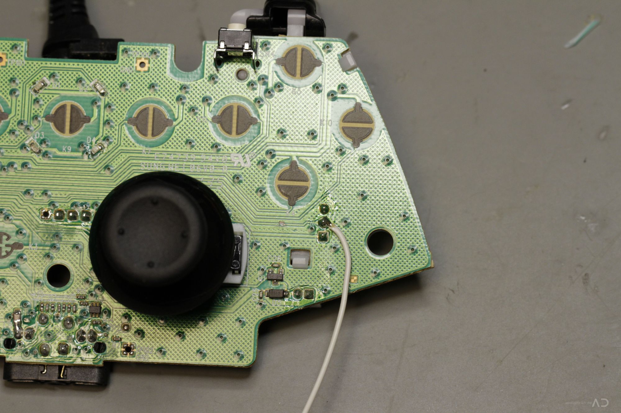
To “close” the circuit another wire has to be soldered on the other end of the break – the easiest way is to use test
Connection to TestPoint 10
[singlepic id=40 w=320 h=240 float=none]
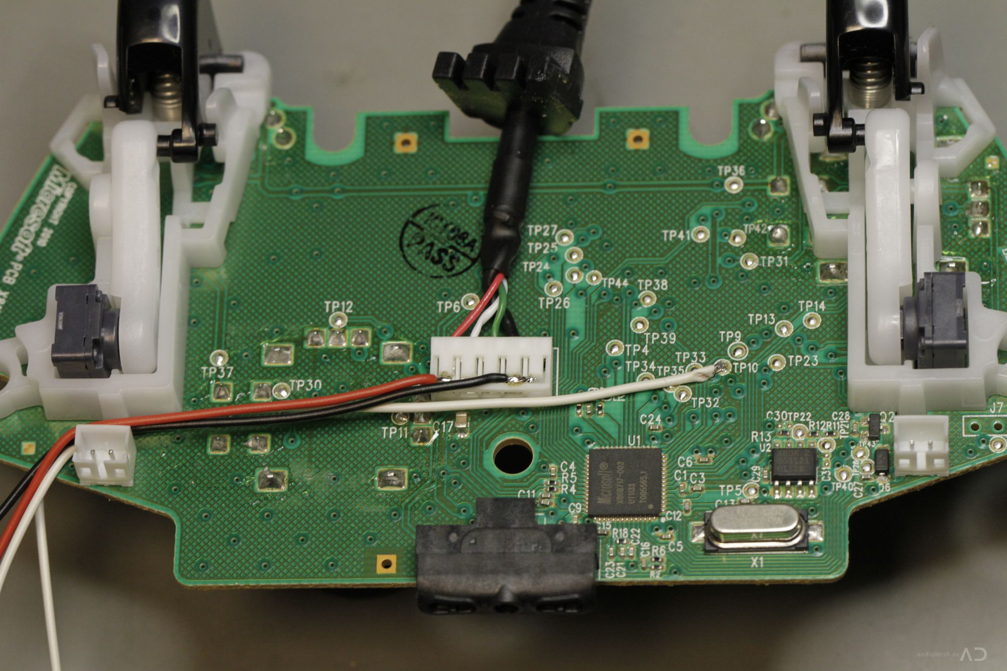
10. Power Supply#
The circuit, including the microcontroller, requires a 5V power supply. Thanks to the USB connection we got the power directly from the usb connection: just solder wires on the red(+) and black(-) wires of the usb connector – that’s it !
USB Connector
[singlepic id=43 w=320 h=240 float=none]
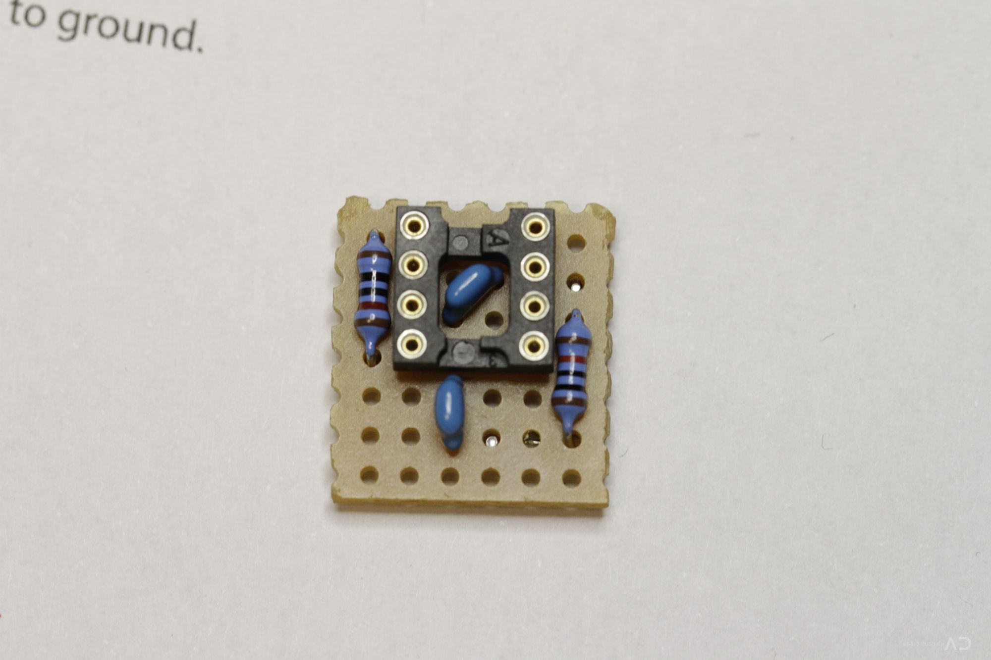
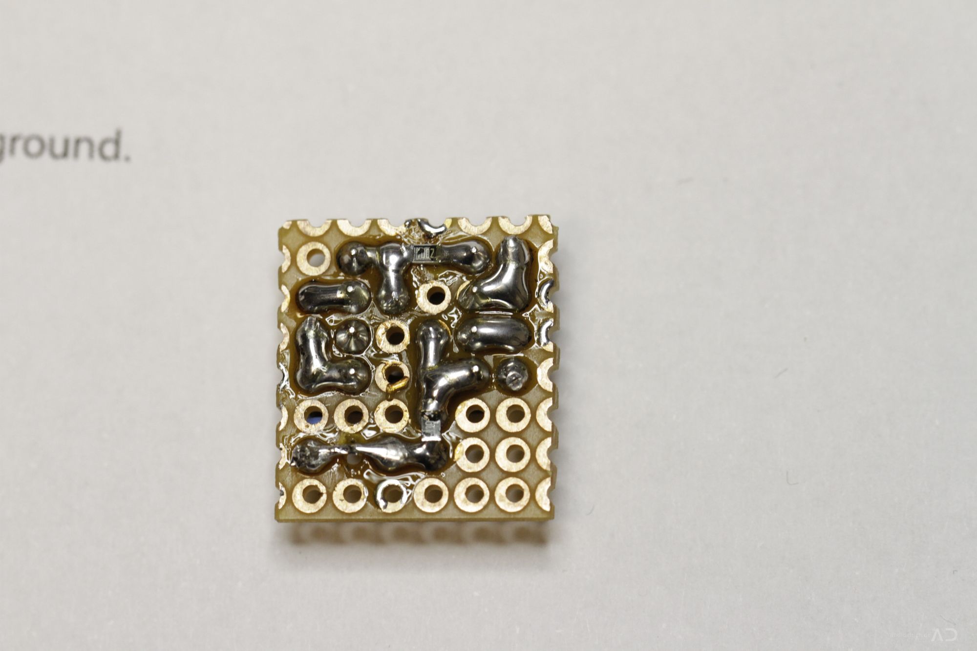
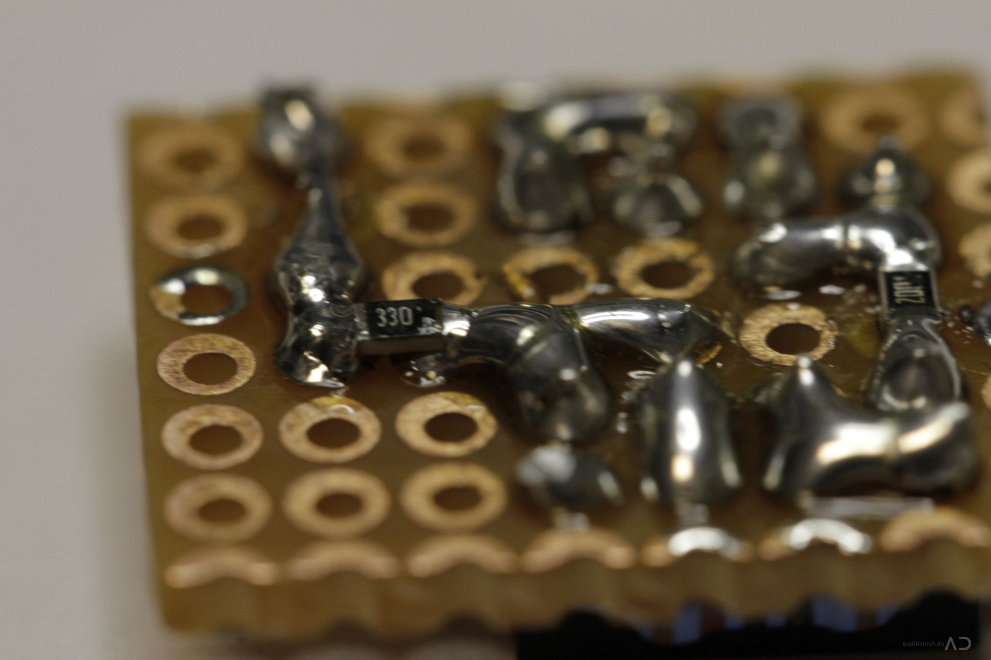
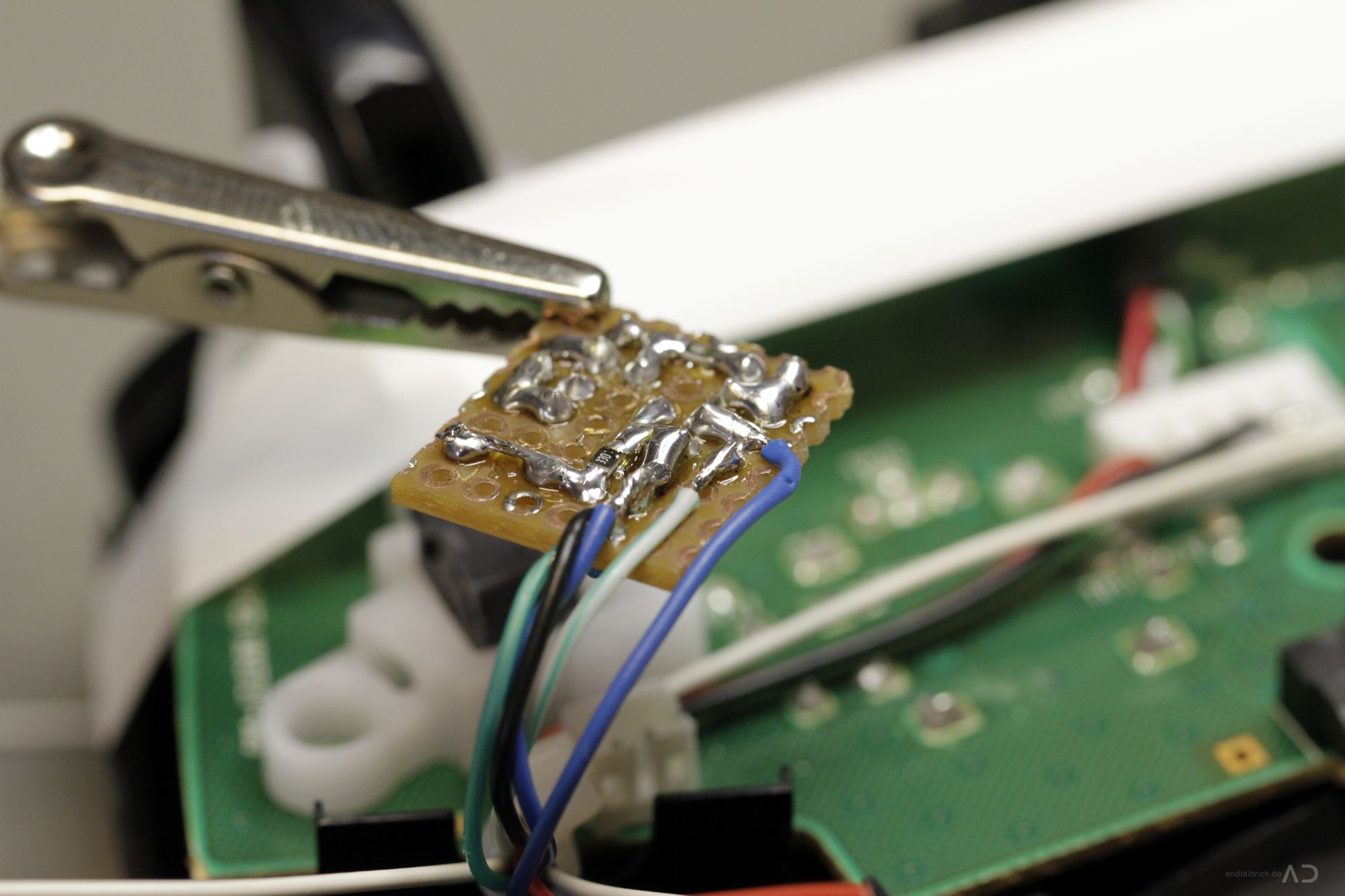
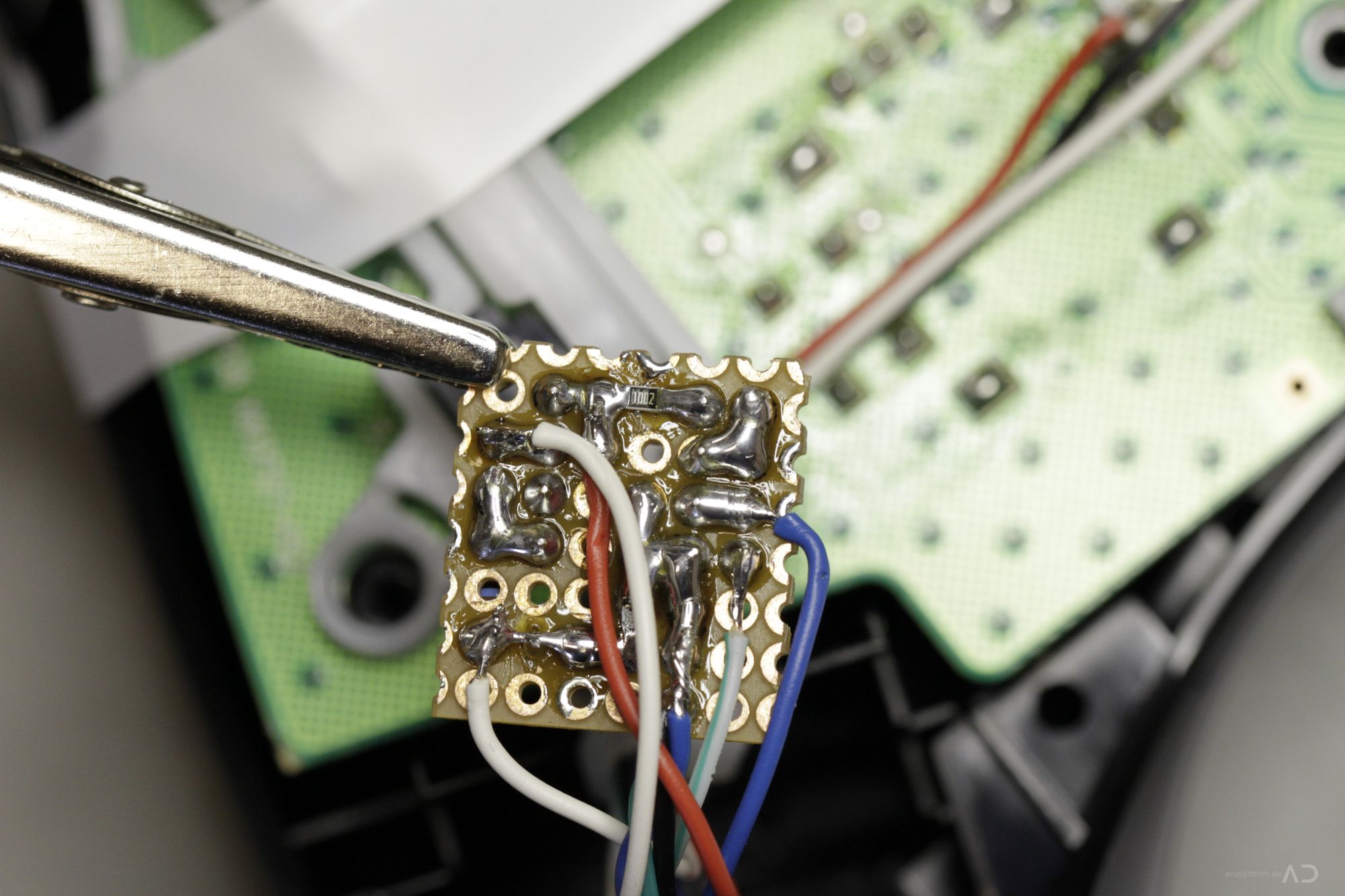
11. PCB Soldering#
I will not provide a step-by-step tutorial how to solder the pcb, because the schematic is kept very simple – just connect the parts as shown in the schematic – that’s it. For the first versions i have used a peace of a prototyping breadboard (dimension of 6×7 pins). If you like, you can use the pcb layout shown in the images, but the layout is only done with an first order lowpass.
The finished PCB
[singlepic id=46 w=320 h=240 float=none]
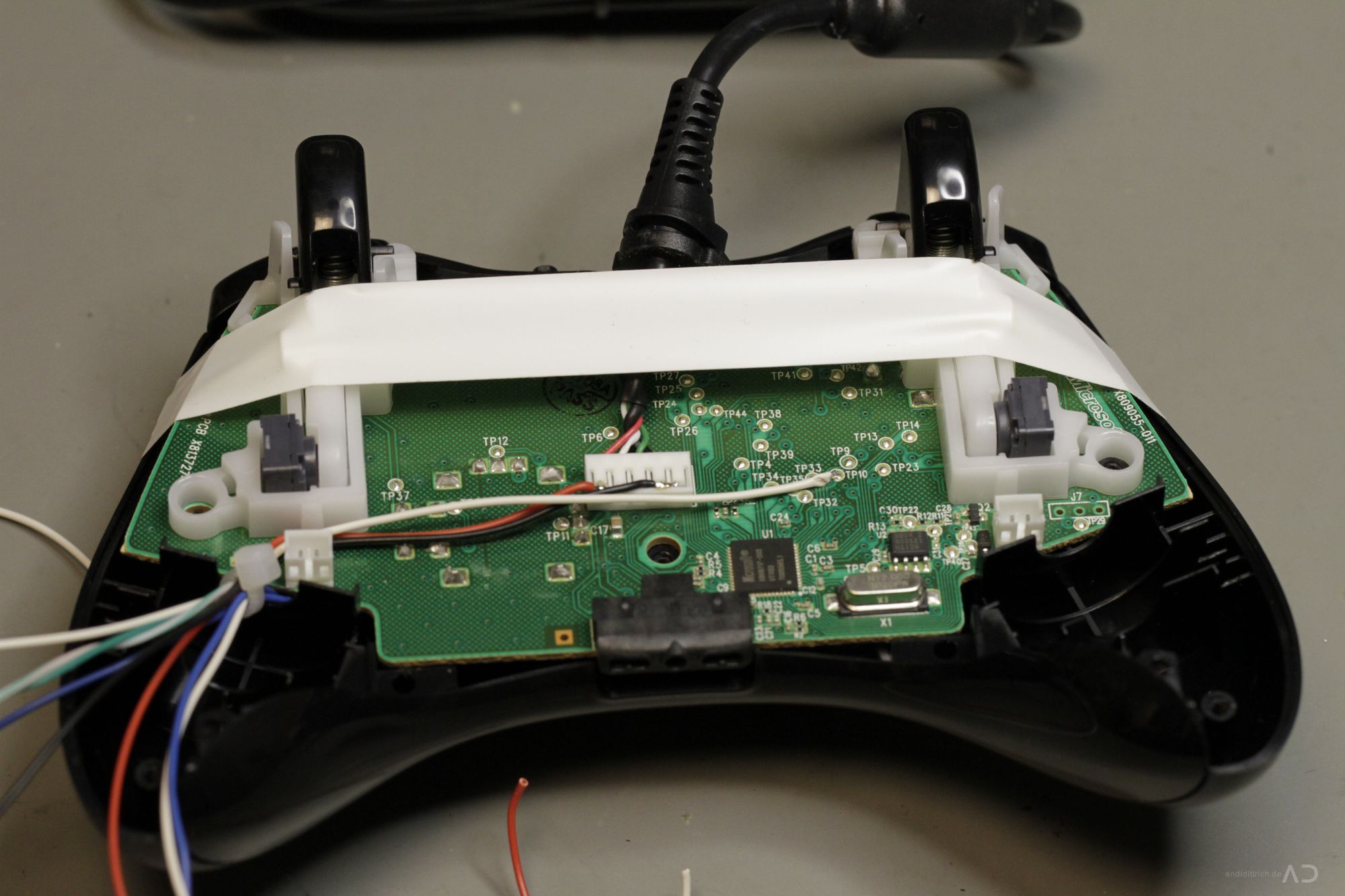
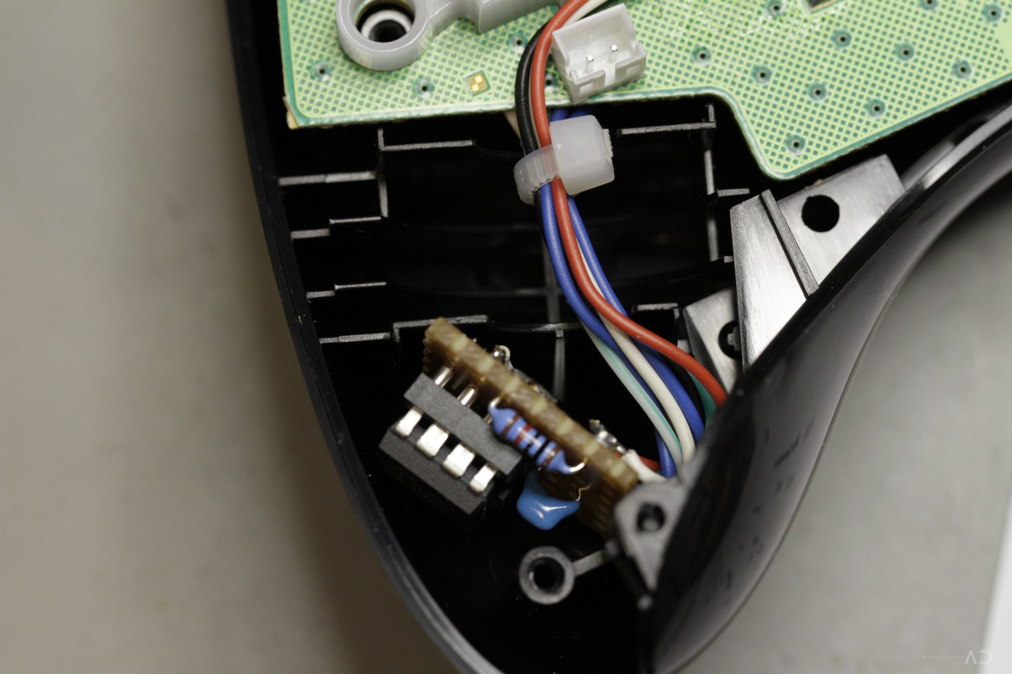
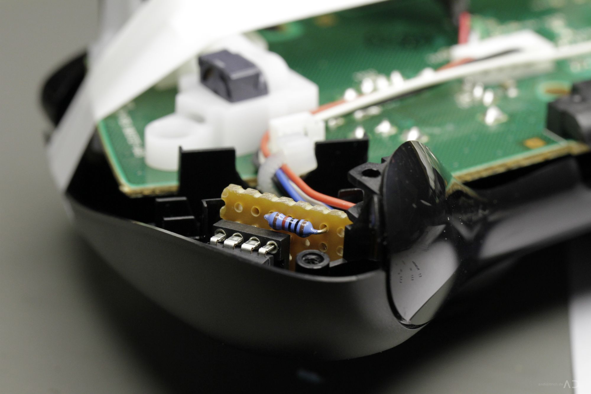
12. PCB Integration#
Now you have to bunch all installed wires below the 2pin molex connetor from the right force feedback drive. All together there are 8 wires (2LED, 2 Switch, 2 Power, 2Trigger). Start with cutting one of them to the prefered length (around 5cm) and solder it to your pcb. A third hand will be very helpful. Cut and connect each wire seperatly and you won’t get any bad suprises like me.. (in worst case you have to replace complete wires if they are to short..). The pcb will optimal fit in the balancing weight housing. You can fix it with tape or something similar.
Wire Bunching
[singlepic id=51 w=320 h=240 float=none]

13. MCU Programming#
Finally you have to download the firmware (HEX file attached to this post) to the AVR microcontroller or build your own software by the attached sourecode. I recommend to use and STK500 with AVR Studio to program the controller but you can also use PonyProg or something similar.
Well this requires a basic knowledge of AVR microcontrollers – if you have no idea how you can do this, ask somebody whos experienced in embedded development or look on the websites of AVR Freaks and Mikrocontroller.net with their great tutorials!
STK 500 setup
[singlepic id=45 w=320 h=240 float=none]
To build the sources i have used the official AVR GCC Toolchain from ATMEL and AVR Studio.
Fuse Settings#
- Internal RC Oscillator 8MHz
- No Clock Divider
- SPI Enabled
- [Extended: 0xFF, High: 0xDF, Low: 0xE2]
Fuses#

14. Reassembling#
Just put the bottom part back on the controller and fasten the screws – be aware of the rubber-keys .. sometimes they will move when fasten the screws and some buttons will not work – in this case, disassemble the controller again and put them into the right place!
That’s it – your finished – now use your own AdvancedRapidFire (ARF) Controller and have fun!
[singlepic id=56 w=320 h=240 float=none]
Demo#
A small video will follow in a few days =) stay tuned!
Full image gallery#
[nggallery id=1]